The Pari XT0 and Attack Organs
Photos and text by Henning Højen.
The following is a slightly edited version of a post to the Hammond Forum on July 2, 2005:
Hello,
My name is Henning Højen. I'm from Denmark.
I just read on a website a question/answer concerning an organ identified as a Pari. The answer expressed doubt about the detailed workings of these instruments, so I'd like to clear this up a bit, as I'm in possession of some schematics on couple of the models, and I have owned both models in the “real-world”. One was an XT0, the other one was named “Attack”. The XT0 had built-in speakers, the Attack was a stand-alone model, similar to the Hammond P-100.
Basically they worked the same way as Hammond, although the generator was constructed from 12 drums with material removed so the tone-wheels were formed. There were up to 8 wheels on each drum, and the number of waves on the tone-wheels was a power of 2 starting at 2 and ending up with 256. The drums were arranged on an axis, 12 in a row, and there were gearwheels on both sides to form the chromatic row. (Somewhere I also have the numbers of teeth on these gearwheels.) The pickups were just 3-4mm iron-rods each wound with a coil, and mounted on a common magnet. There was filtering on each single pickup to avoid interference and hum.
There was a phase-shift-line to form the basic vibrato-system, and it had the scanner too to detect the points in the phase-shift-chain. The scanner was very simple, it was just a rotating and a stationary condenser; very simple — just like the drawing in the Hammond-schematics! The scanner was driven by an O-ring belt from a pulley on the generator.
The motor was a Papst, and the connection to the generator was an O-ring belt too, so how they got the organ into standard-tuning I don't know!
The XT0 was in fact very similar to the Hammond M100 in the sound, and had the same facilities, among these a very good percussion.
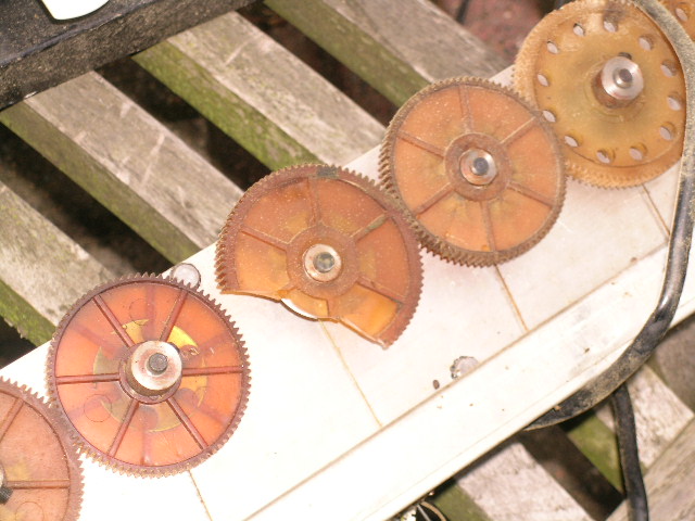
The gearwheels were the absolute weak point in these instruments — it all came to an end when the teeth were torn off. The bearings in the generators needed oil and this caused the wheels to deteriorate and at last to be destroyed, at which point a part of the organ became silent. Production of the organs stopped during the '70s and hence replacement gearwheels became unavailable.
I tried to piece together the electronic part of the organ with a generator from am Hammond L-100, but there was apparently a mismatch in impedance, so it was not a big success Okay, it could play — just very weakly! Some years ago I bought a Hammond M3 and got rid of all the problems.
If anyone is interested I have schematics on both models, I would be very happy to ship copies.
The very best Regards Henning Højen henning@hojen.net.
Pari is Now Making a New Organ
As of late 2006, Pari has been manufacturing a new organ, the model K-61, a nice looking two manual B-3 clone. (They also make tube-powered Leslie clones to go with it.) More information about the K-61, as well as pictures can be found on the HammondWiki Pari page.
Pictures of an Attack
The Pari Attack model was a really refined model compared to the older XT0. The layout of the electronics is really nice, and there was a very nice general layout of the whole unit which facilitates service. Due to the modular design, I would guess that the manufacturing process was not necessarily done at just one location, rather the different parts could be made elsewhere and put together in an assembly location.
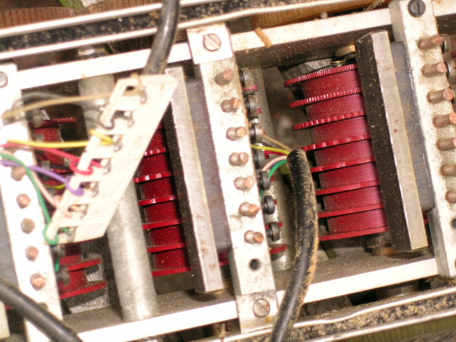
The “tone-wheel-drum”. The pins — up to eight for each drum — are the pickups, the coils are underneath close to the tone-wheels. The magnet is positioned on the side of the retainer for the pickups — it is the dark part visible in the photo — a steel plate is glued to the opposite side of the magnet, apparently to give a more uniform field. The white connector goes to the filter-board, which is mounted separately.
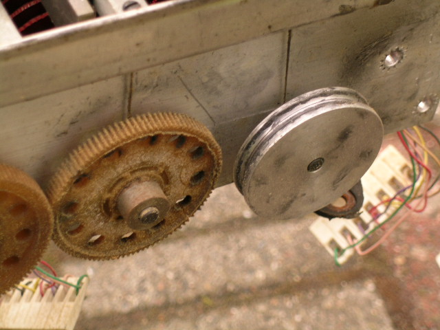
The pulley for the drive belt (a long O-ring.) The generator is driven from a Papst-motor.
Pulley for the scanner. The scanner pulley is hidden behind the aluminum cover. The scanner detects the outputs from the phase-shift line (located elsewhere in the enclosure.) Note the use of a printed circuit board (PCB) (at far end of the scanner in the photo, with cut-off wiring.) The shaft of the scanner picked up the signal, and a carbon-ring surrounding the shaft conducted the scanned signal back into the scanner-amplification circuit, which is a bit different than the “normal” amplification circuit.
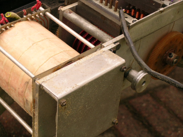
The misery of the PARI. The rest of the generator is silent.
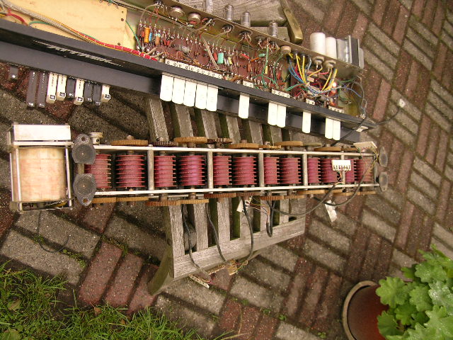
The whole generator, bottom view.
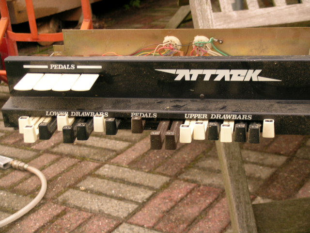
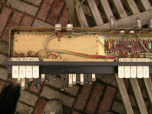
The draw-bar section.
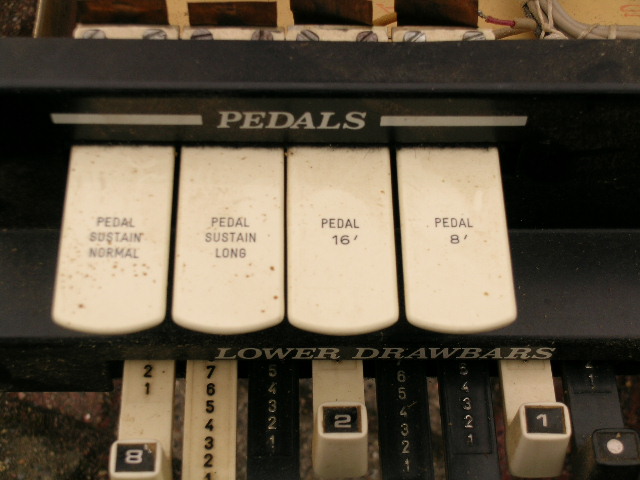
The pedal control tablets.
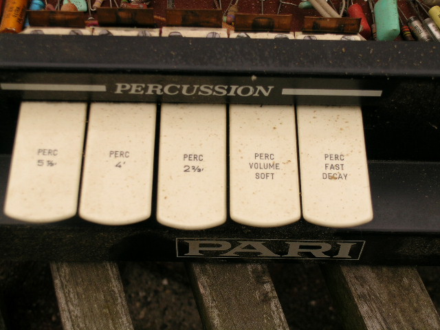
The percussion control tablets. Note the choice of three harmonics for percussion.
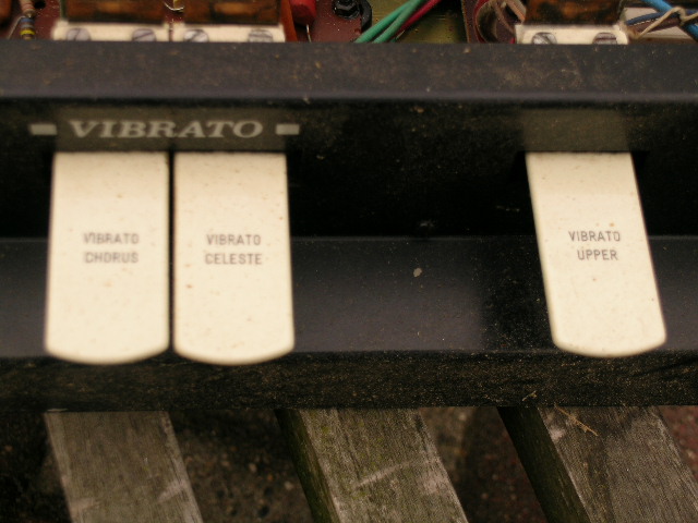
The vibrato control tablets.
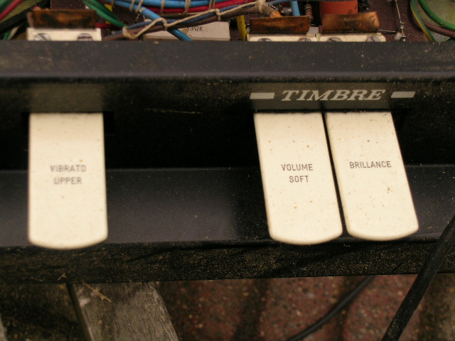
The volume and brilliance control tabs.
The draw-bar section. The draw-bars operate as voltage-dividers, built up with fixed resistors in steps corresponding to the figures on the draw-bars (While Hammond used a more expensive solution (resulting in lower noise) with tapped transformers from the M series and up, the cheaper Hammonds, L100 and P100, used the resistive divider solution, like the Pari.)
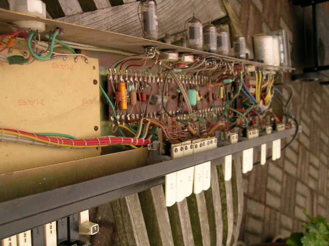
An overview of the whole electronics.